
Xpress XQ10 Build Tips Review and set-up
https://www.thercracer.com/2020/10/xpress-xq10-build-tips-review-and-set-up.html

The touring car platform is in a constant world of development. The latest trend is moving the motor towards the centre of the chassis. When coupled with equal length drive belts, the power delivery should be better, allowing more mid corner power & a better weight distribution. Several manufacturers have tried this before. Notably Schumacher in 2000 with the axis, and Tamiya with the TA05 in 2004 that created the centre pulley/ equal belt design used by many of the 2020 chassis of today. It never really caught on at the time, I suspect that a central motor is more suited todays brushless motors & lipo batteries
The Xpress XQ1 was an incredibly competitive touring car & served drivers well around the world for around 3yrs. To fil a stop gap, a mid-mount conversion was offered. This seemed to take on a few updates, it also allowed the team to add those developments into a completely new chassis, hence the creation of the XQ10
Although the chassis has been available for a few months, other projects have delayed my purchase. I will be looking to concentrate on touring car racing over the winter, so I can get the car set up before the season starts
As with all my builds, I will highlight areas of interest & concern. You do not need a step by step guide!
As with all my builds, I will highlight areas of interest & concern. You do not need a step by step guide!
Instruction manual/ part bags
This is a vast improvement over previous Xpress chassis I have built. In a previous review (XQ1S), the manual had you opening multiple bags for 1 step of the build. This would lead to a lot parts being left on the table which is very confusing. The XQ10 manual is incredibly detailed & nothing has been left out. It even notes area you need to apply thread lock. The screws are now in a separate bag which is especially usefulTurnbuckles
They plastics are now a grey coloured low friction material.
They were easy to build & provide a silky-smooth action
Differential
The only difference is the addition of the new x rings.
These will help prevent leaking & make a better seal. I found that they required less force to sit in the housings as the edges are flatter than a conventional o ring
Layshaft
The pulleys now adopt 3 pins on each pulley to secure the spur gear. It does away with bolting the gear to the layshaft to prevent warping/misalignment. If you decide to fit an aftermarket spur gear, just be careful that the gear has 6 holes to locate otherwise, it will not fit.
The manual also highlights the fact that aftermarket spur gears are different in size, so includes 4x0.2mm shims to take up the play in the layshaft, a nice touch in my opinion. You want to have next to no play, but make sure there it is free with no binding. Although 0.2mm shims are provided, I needed a 0.1mm to fit a Xenon spur gear with a total of 0.7mm of shims.

To check the rotation properly, I advise fitting another screw around the back with another screw & just nip it up. You are then able to check the free play with no issues. Remember to remove the screw as you need to fit it to the motor mount!
Steering/ servo mount
The previous chassis had a 1-piece steering /servo mount. This allowed the user to choose between floating steering or fixed.
This has been eliminated to separate mountings with fixed being the only option. Although I preferred floating on some tracks, I guess it’s generally decided that fixed is the better option

The lower bellcrank posts have bigger nuts to get a spanner on to tighten them to the chassis. Tamiya 5.5mm spanner to the rescue!

I fitted a brand new SRT BH815S servo with no issues. It comes with a short lead, so no need to modify. I also fitted my preferred Tamiya 51000 hi torque servo saver with 3racing alloy horn suited for indoor racing
Bulkheads & shock towers
After racing the cars for 18 months, we have found that cutting the 1-piece bulkheads in half to adopt a more conventional setup generated more flex & traction. Whilst there was no issue with alignment, it was modification we had to do. The upper bulkheads ran the risk of tweak as the shock towers were only held on with 2 screws.
The XQ10 now comes with split bulkheads. I used a Techra setup wand to align the bulkheads. Whilst I would of like more holes to be aligned, 2 were enough. The upper bulkheads are also split for the same reason. The XQ1 used the upper bulkhead & 2 screws to seat the shock towers. Now, there are 4 screws to secure the towers. The towers are also low profile for the short shocks
Chassis plates & layshaft mounting

The chassis plates have a lot of cut outs & screw holes for lots of flex adjustments. The lower deck also employs an alloy T bar to adjust the level of flex. The top deck has a composite flex member for the front end. Both parts can be removed/ adjusted to control the levels of flex

Unfortunately, the centre motor post would not line up to fully clear the rear belt. We will see how if it causes an issue.

The layshaft bolts on with no issues, but make sure the belts are fitted in the right positions before the top deck is fitted. There is also a rear belt idler to avoid clearance issues
Suspension
The lower suspension arms are of a different design. The arms have fewer cut outs which in turn makes them stiffer. The outdrive pins are now fixed with a slotted pin with a grub screw. This reduces future costs as the pin can be replaced when worn rather than a complete shaft. For the rear, you can also fit the blades much easier. On the previous cars, you had to stretch the blades over the pins in place, you would snap a few when fitting them. I would recommend more thread lock than you previously use, more on that later!
When fitting the driveshafts, I always use a set up thumb screw to fully seat the bearings & make sure the hex hub is straight before tightening up the small screw. A trick I saw from Alexander Hagberg. If it’s good enough for him, its good enough for me!
The rear suspension arms were binding when I fitted the rear pivot block. I ended up swapping the rearmost 1.0mm shim for 0.85mm of shims. They then dropped under their own wait with minimal free play
Shocks
These also adopt the x rings like the differential, so a silky-smooth operation with less chance of leaks.
There is a super short damper design which is in common place in todays touring cars. I built them with 450cst oil & 4-hole pistons. They are mounted to low profile shock towers; the front is pretty much flat in design.
Electronics
I previously mentioned I fitted a SRT servo. For the power, I fitted my preferred esc, a Hobbywing 80a stock spec. A perfect choice as it is a very small unit & provides more than enough power for blinky racing.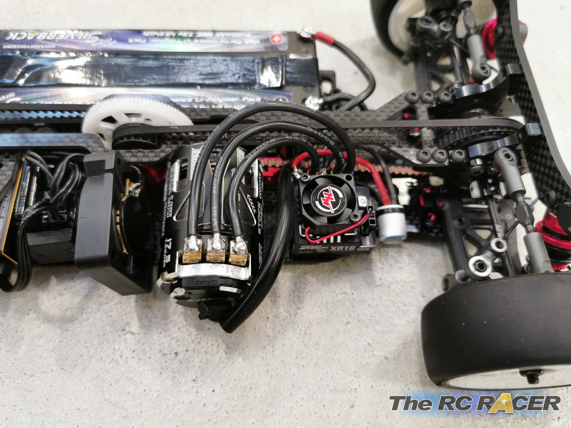
I just had to get creative with wiring locations. The battery terminals run through the chassis plates; I ran the motor wires in a fan style as if I laid them flat the wires would cross the belt.

The motor mount has a slot for the receiver harness to travel pass the motor to connect to the receiver. I fitted a Sanwa RX492 receiver & a MRT ptx to finish the electronics. I employed a Silverback 6400mah lipo. Regular sized as the weight is quite close to the weight limits, so no need for a shorty pack!

The rest of the car built the same as the previous car with no issues. Once finished, I put a base setup onto it & was ready to hit the track
Track test
Although the government guidelines have restricted some clubs, my local club (Bristol model car club) are still able to race. Social distancing is being practiced. We have to race with reduced entries, but its great that racing can continue!

I ran my bodyshells from the XQ10 & some previously used tyres. The posts are exactly the same as the previous car in terms of position. I used a Zoo racing DBX bodyshell & some old Sorex tyres
I did a few minutes of practice just to get the tyres settled in & get a feel for the car. The rear was loose at higher speeds, I just put this down to low grip.

The first qualifying session went similar to practice. The rear was still snapping at high speeds, but there was lot of front grip, I was literally hitting every apex & I felt this was a contributing factor to the snappy rear.

For round 2, I applied half additive on the front tyres & swapped to a Bittydesign Hyper bodyshell. The car was so much easier to drive! I was able to push into the corners without the front diving into the barriers.

Unfortunately, after a few minutes, the car came to an abrupt halt. Upon inspection in the pits, I found a front drive shaft pin had worked loose, slid out of the outdrive & got stuck between the suspension arm. I tried to bend it back, but it’s a very hard steel, so I managed to borrow a pin from a used XM1 Drive shaft. When building the car, I used a small amount of threadlock, I guess it was not enough. I applied a little bit more than usual & the pin didn’t move for the rest of the evening

For round 3, I just did the same tyre prep as I didn’t have a full run in round 2. The car was great but would still want to step out at high speeds. I managed to take pole position, so was pleased. I raced the final with no changes as I wanted to know if the high speed oversteer was just a grip issue, it was still present
After the meeting, I spoke to the team to see of anyone else has experienced this issue. I will be removing the rear T bar as this allows more rear flex

Here is my base set-up for the XQ10
For round 3, I just did the same tyre prep as I didn’t have a full run in round 2. The car was great but would still want to step out at high speeds. I managed to take pole position, so was pleased. I raced the final with no changes as I wanted to know if the high speed oversteer was just a grip issue, it was still present
After the meeting, I spoke to the team to see of anyone else has experienced this issue. I will be removing the rear T bar as this allows more rear flex
Set-up

Here is my base set-up for the XQ10
Adjustments/upgrades
Going forward, I will be looking to adjusting my setup & learning the new configuration. I will be removing the T bar as a start & will be testing all the levels of flex available to see what effect it has on the car.I will be fitting a set of titanium screws to lower the centre of gravity. I have seen that there is a set of titanium front spool outdrives which utilizes blades. Apart from that, I can’t see anything else that needs to be upgraded. I will look at adjustment options to adjust flex.
Overall summary
In terms of the build, I didn’t really feel that were any issues. The Xpress instruction manuals have improved over the last few years & every aspect of the build is well covered & detailed. Apart from a few shim adjustments & some smoothing of the plastic mouldings, the build was a pleasure to build
In terms of the driving style, you can feel that the weight has shifted off the rear of the vehicle. Where the traction would come straight of the corners, the mid mount allows more corner speed but you won’t have to wait for the car to be near the exit of the corner before the power can be applied.

For me, I will take a few weeks to adjust my driving style to suit the new weight balance.

However, I believe that I will gain more corner speed as the car can driven harder into the corners without the rear creating a pendulum effect.
The Xpress brand can hold itself up against the more established manufacturers currently available. Although it’s an unconventional option, its definitely worth looking into.


Use 8-12k cst oil for differential ;)
ReplyDeletePersonally, the rear flex setup determines the amount of rotation the car has. The more flex in the rear, the more rotation you get and may compromise high speed stability.
ReplyDeleteIf the rear steps out a high speed, just add a 1mm shim under the inside camber link, and done, the rear will be planted. This mod alows the rear to roll more. I tune front a rear grip that way on all my xpress cars.
ReplyDelete